Saturday, August 7, 2021

New Project

Hallicrafters SX-101A Communications Receiver

Saw this for sale on ebay and just could not resist. This is one of ham radio receivers I have always coveted. This one will need a little work (see dial pointer) but seems in very good cosmetic condition. No sign of rust and, for its age (over 50 years old), isn't as dirty as some similar aged electronic equipment I've seen. It is a true "Boat Anchor," weighing in at 75lbs. I've read that manufacturers at this time created these heavy weight behemoths to help with frequency stability.

There is a pic after it was removed from its cabinet:


It will need to have a number of the old electrolytic and paper capacitors replaced, as well as a general going over for out of spec components.


Thursday, June 17, 2021


Swan 350C

I found this Swan transceiver from the 60's on eBay for an excellent price with free shipping! It is in excellent condition but lacks the necessary power supply, so that is my next quest. I'll replace some of the original electrolytic capacitors and it should be good to go.

 Heathkit Cheyenne Transceiver

Picked up a 60's transceiver at a ham swap meet. It needed some work, including replacing some of the electrolytic capacitors, rewiring it for 6.3VAC tube filaments and replacing the changeover relay. I also changed the microphone jack to be compatible with my Astatic D-104 8-pin connector. I 3D printed an adapter (blue plastic piece) to allow the smaller diameter jack to fit the larger original mic jack hole. Also, this transceiver requires an external power supply, so building one will be required.

Replaced the relay on left that was "chattering" with the one on the right.


3D printed adapter for 8-pin mic jack

Power Supply for Cheyenne Transceiver

Power supply provides 600VDC, 300VDC and 6.3VAC

I had some of the PS components on hand, but needed a transformer, the 20Watt resistors and the Cinch-Jones 6-pin connectors that the Cheyenne uses for power input. The voltage output is a little high with out a load but should be within specs with a load.

Found one of the tubes bad so I just ordered replacements for all the tubes except the 6146 power output tube. I have another on hand in case that one is bad.

Next steps are to get the Cheyenne aligned.


Saturday, April 17, 2021

Yet Another 40 Meter Transceiver Project.... but this one seems to be working.... a bit

I found another transceiver project by someone who has inspired me over the past year. Dave Richards (AA7EE) has an amazing site that has quite a wide variety of his projects, including this 40 Meter transceiver. While I was using Dave's site for guidance, the transceiver circuit was originally inspired by Peter Parker, VK3YE. I've built several of Dave's projects and learned a lot from what he has done and the techniques he uses in electronic construction. 

The audio amp is in the upper center-left. The VFO is located lower left using a variactor with the 10-turn potentiometer in the lower right (blue) for tuning. Center right is the transmitter, along with band-pass filters. Upper right is the relay to switch both power and signal between receive and transmit.


A little better view of the audio amp (left) and the VFO (right). In the center is the microphone amp and 9 volt regulator supply for the LCD display. The red wire that doesn't seem to go anywhere is the pickup for the frequency display.


Volume control is upper left with the mic jack below. The toggle switch is receive/transmit. Large knob is tuning with the 10-turn pot.

The receiver works but doesn't produce adequate volume, so I'm still trying to figure out why. I know the transmit function works but I'm looking for a proper microphone so I don't know what the quality of the signal will be. It will probably need some work as well.


Monday, March 29, 2021

Yet Another Transceiver Project

Discouraged with my efforts to get the transceiver below working, I have embarked on a new transceiver project, thanks to the postings and helpful hints of Peter Juliano (N6QW) and his extensive website of transceiver projects. Some of these projects are just too challenging for me, at least until I have some successful outcomes with the transceiver projects I've been working on! Peter's projects are incredible!

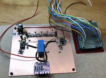
In order to get acquainted with a circuit, I often redraw it, and in that way I have a better idea about how to tackle layout and the order in which I will complete the project. Below is my schematic of the transceiver. Some modules are not yet represented. I will build this part and attempt to get the receiver working before I move on to the transmitter. The shaded areas are what I have completed so far, along with the bottom portion with the Arduino, display and Si5351 signal generator module.


Here are pics of the central board and Arduino controller.


Got the Arduino programming to work after several days of troubleshooting. Some of the code protocols had been revised in the past couple of years and it took forever to figure out that the encoder (the thingy to the left of the display that controls the frequency that appears on the display) was faulty. Replacing the encoder solved the problem.

Still working on this project...


Wednesday, January 27, 2021

Code Practice Oscillator

I'm having only limited success with the 80 meter receiver project. Some of the modules work but I'm having problems with the mixer and product detector. I have built 5 VFOs trying to get one that is stable enough for reliable operation. While they all work to some degree, there seems to be too much frequency drift. So.... I've been working on a couple of other projects to take a break from that project.

I've been working on re-learning morse code, so I though I would build a code practice oscillator. Some pics of that project are below:


While there are many basic circuits for constructing a CPO, the sound that they make is very disappointing. So this was a circuit that creates a true sine wave signal so the sound is quite satisfying.


The finished CPO

With the CPO finished, it was time to start another project. I found a schematic for a 40 meter ham band receiver that uses varactors for tuning. Traditionally, radio tuning was accomplished with variable capacitors, sometimes large mechanical devices that are becoming more difficult to obtain and often expensive. Varactors are semiconductor diodes that change capacitance with a varying voltage.

Like a previous project, I found an interesting circuit on AA7EE's web blog that seemed to fit the bill. It is a regenerative 40 meter ham band receiver.


The finished project. And it works!


New Project Hallicrafters SX-101A Communications Receiver Saw this for sale on ebay and just could not resist. This is one of ham radio rece...